Controlling Devices
The following sections cover functionality and settings relating to specific device types. The system supports a range of field devices including GPO's and smart lights.
Device Control#
The top section of controllable groups and devices is populated by a control panel. The control panel in device group page of Figure 13 is shown more clearly in Figure 11. This control panel exists for all controllable groups and devices. For non-controllable groups and devices this control panel is absent. Above the panel is a link titled "Permissions" with an eye next. This provides user’s access to the group’s permission settings. From here group admins can assign permissions for user and user groups on the device group deciding what actions users can perform on the current group. Permissions are explained further in 14.
Below that we have the groups control buttons. The first marked "Schedule" provides a link to a page that allows us to assign and un-assign schedules to the group. Schedule management will be explained further in 5.
Following that we have the command mode button marked "override". This button can be toggled between override and inherit. In inherit mode groups and devices inherit all settings including control mode, state and schedules for their parent group and cannot be separately altered. Items in this mode have all other controls disabled as seen in Figure 12 to prevent such separation. Groups and devices in this command mode are essentially slaves to their parent group. In override mode devices and groups become independent from their parent and can separately alter their control mode, state and schedules. When the command mode is switched to override users will be able to alter the control mode and state of the device or group. For root devices groups such as in Figure 13 the command toggle is disabled and fixed in override mode. This is because there is no parent group to inherit from.
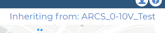
Controllable device/groups show an ‘Inheriting From’ label on their pages showing the ID of the group/device they currently inherit from (see Figure 10). Note that for items in override mode this label will show that it inherits from itself.
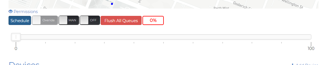
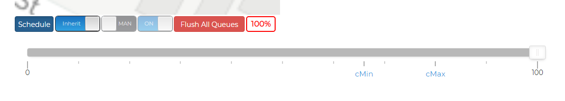
Users can use these two command modes to construct control hierarchies over their devices and groups and more specifically configure their IoT devices in the field. For example smart lights placed close to residents can be overridden to dim to lower levels during the evening to prevent keeping people awake, or an Eastern group sector of GPOs might turn on earlier in the evening to display Christmas lights to the public. The next button in Figure 11 marked "MAN" is the control mode button. As explained above this dictates if the device or group is in an automatic scheduled state or a manual mode. In automatic mode devices and groups are controlled by a daily schedule and their state may alter throughout the day. In manual mode devices and groups will remain in a fixed state. The next button marked "ON" provides users with the ability to toggle the state of the device or group between on or off. For smart lights more fine levels or dimness can also be selected using the dim slider below. These state controls are only active when the device or groups is in override command mode and a manual control mode i.e. when the item is operating independently and not being controlled by a schedule.
Preceding the on/off button is flush queue button that allows operators to clear uplink queues for the application gateways. This may be necessary as low transmission rates in Class A LoRaWAN networks can lead to a backup in uplink messages if users try to send to many commands at once. Warning: Using this button will cause the device and/or group's state to be out of sync with real life device state for a period of time. In Figure 11 user will also see a dim badge in red and white indicating the current dim level of the device or group. This only appears for smart light devices.
Triggers#
Devices which support triggers can implement functionality to overide controllable devices based on recieved data from other devices (trigger device). Whenever a device is triggered it is set to manual mode and will overide the current controls For example Lets ake the case of turning on a GPO Controller when a Temperature Humidity Device recieves a temperature over 15 degrees.
To set a trigger click the trigger button show in the blow image from the device page. in this exampele we will trigger the gpo device to turn on when temperature from a Temperature humidity exceeds 20 degrees.

To configure the trigger fill in the form shown below in the following steps:
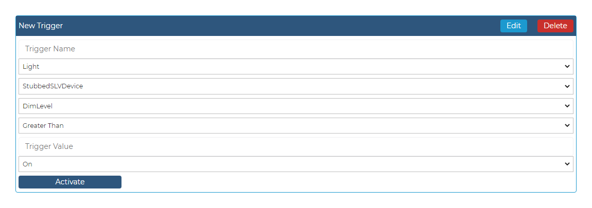
- Input a name for your trigger. This should be a recognisable If for the trigger that describes its purpose. ie Temperature Trigger
- Select the device type of the trigger device witch will trigger the controllable device. ie TempHumidity
- Select the id of the dvice which which trigger the controllable device. ie DeviceId
- Select the condition ie greater than, equal to or less than. ie Greater Than
- Select the value that will cause a trigger on the controllable device. ie 20
- select the action that the trigger will cause ie On
- Click activate.